 | –≠–ª–µ–∫—Ç—Ä–æ–Ω–Ω—ã–π –∫–æ–º–ø–æ–Ω–µ–Ω—Ç: K1100S | –°–∫–∞—á–∞—Ç—å:  PDF PDF  ZIP ZIP |
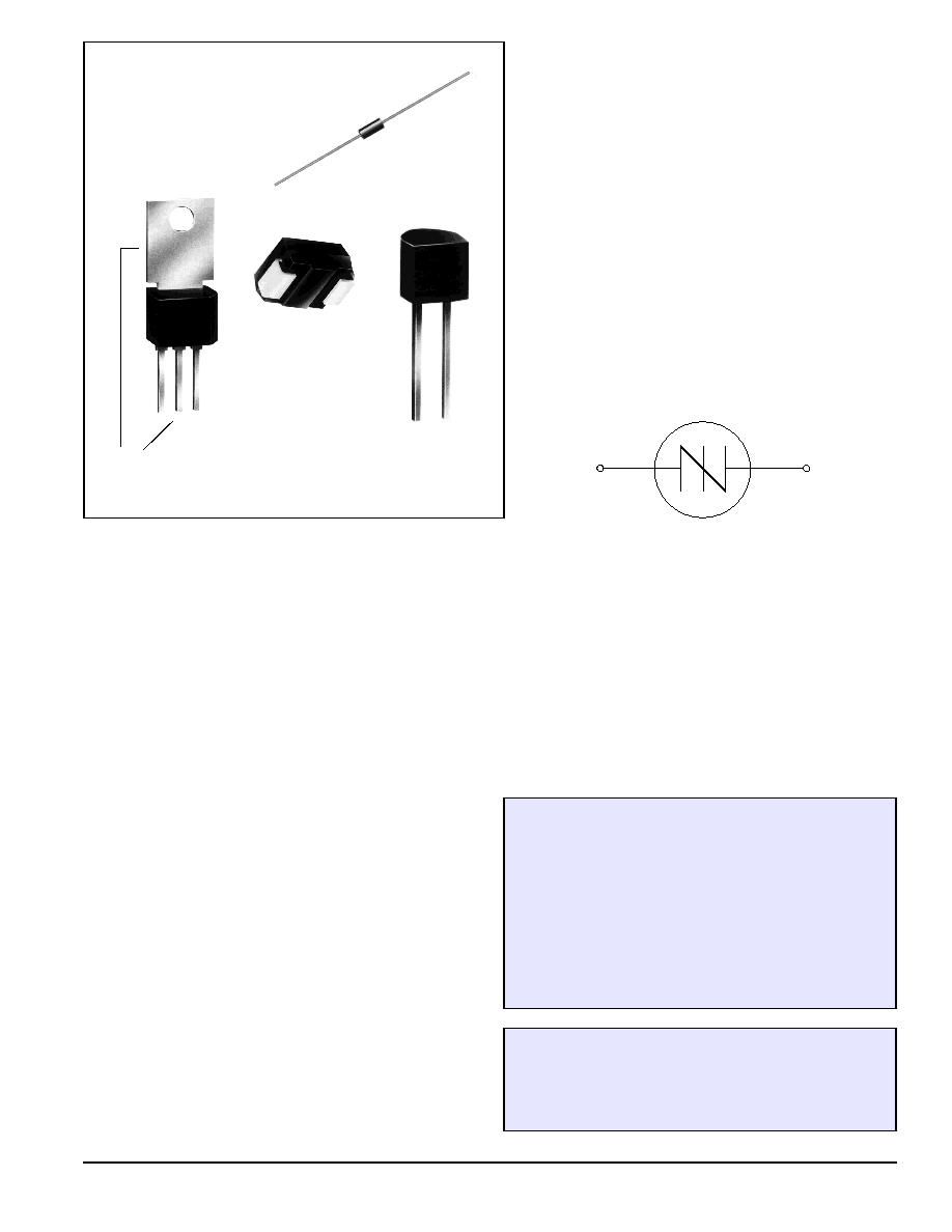
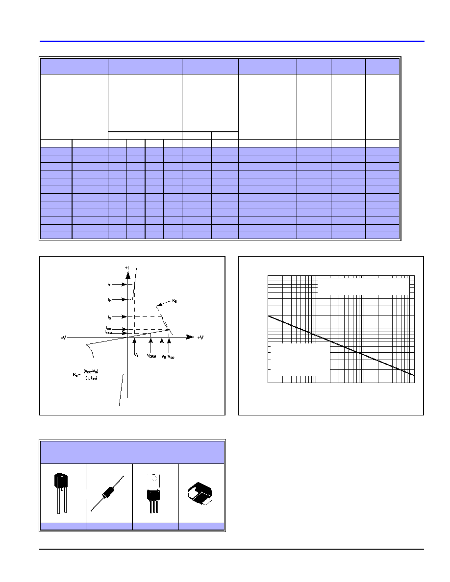
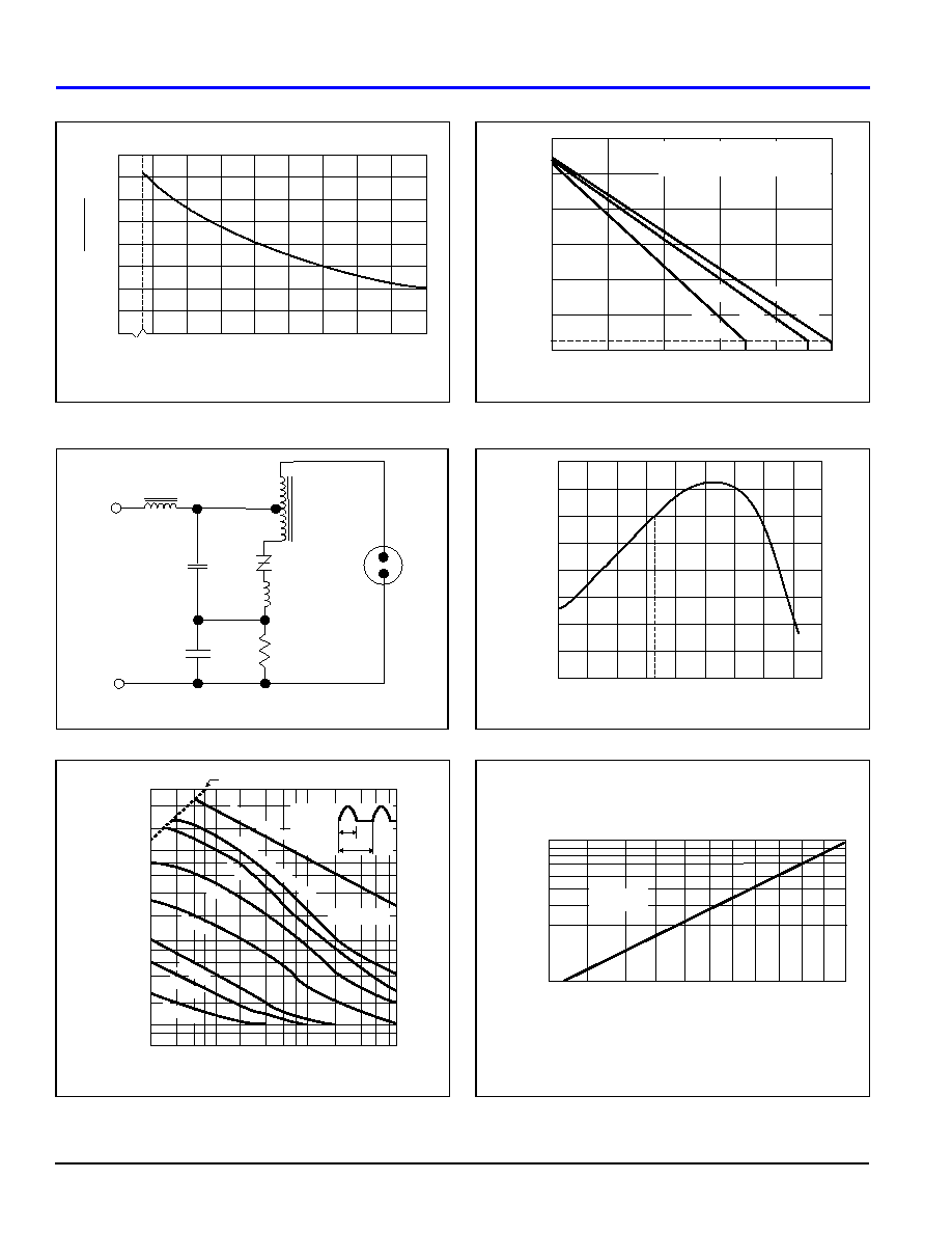
TO-202AB
Type 1
TO-92
Type 70
DO-214AA
Surface Mount
DO-15X
Axial Lead
Do not use mounting tab
or center lead,
electrically connected
Teccor Electronics
9-1
SIDAC
(972) 580-7777
SIDAC
(95 - 330 Volts)
9
General Description
The Sidac is a silicon bilateral voltage triggered switch with
greater power-handling capabilities than standard diacs. Upon
application of a voltage exceeding the Sidac breakover voltage
point, the Sidac switches on through a negative resistance region
to a low on-state voltage. Conduction will continue until the cur-
rent is interrupted or drops below the minimum holding current of
the device.
Teccor offers the complete voltage range (95-330) over three dif-
ferent packages:
∑
TO-92 (95-280 volts)
∑
Axial lead DO-15X (95-280 volts)
∑
Surface Mount DO-214AA (95-280 volts)
∑
TO-202AB (190-330 volts)
Teccor's Sidacs feature glass passivated junctions to ensure a
rugged and dependable device capable of withstanding harsh
environments.
Variations of devices covered in this data sheet are available for
custom design applications. Please consult the factory for more
information.
Applications
∑
High voltage lamp ignitors
∑
Natural gas ignitors
∑
Gas oil ignitors
∑
High voltage power supplies
∑
Xenon ignitors
∑
Over voltage protector
∑
Pulse generators
∑
Fluorescent lighting ignitors
∑
HID lighting ignitors
Features
∑
AC circuit oriented
∑
Glass-passivated junctions
∑
High surge current capability
Electrical Specifications
SIDAC
9-2
Teccor Electronics
(972) 580-7777
General Notes
∑
All measurements are made at 60Hz with a resistive load at an
ambient temperature of +25∞C unless otherwise specified.
∑
Storage temperature range (T
S
) is -65∞C to +150∞C.
∑
The case (T
C
) or lead (T
L
) temperature is measured as shown on
the dimensional outline drawings. See "Package Dimensions" sec-
tion of this catalog.
∑
Junction temperature range (T
J
) is -40∞C to +125∞C.
∑
Lead solder temperature is a maximum of +230∞C for 10 seconds
maximum;
1/16" (1.59mm) from case.
Electrical Specification Notes
(1)
See Figure 9.6 for V
BO
change vs junction temperature.
(2)
See Figure 9.7 for I
BO
vs junction temperature.
(3)
See Figure 9.2 for I
H
vs case temperature.
(4)
See Figure 9.14 for test circuit.
(5)
See Figure 9.1 for more than one full cycle rating.
(6)
R
JA
for TO-202 Type 23 and Type 41 is 70∞C/watt.
(7)
T
C
90∞C for TO-92 Sidac and T
C
105∞C for TO-202 Sidacs.
T
L
100∞C for DO-15X and T
L
90∞C for DO-214AA.
(8)
See Figure 9.15 for clarification of Sidac operation.
(9)
For best Sidac operation, the load impedance should be near or
less than switching resistance.
(10) Teccor's new, improved series of sidacs is designed to ensure
good commutation at higher switching frequencies as required in ignitor
circuits for high intensity discharge (HID) lighting. A typical circuit
for a metal halide lamp ignitor is shown in the schematic, Figure
9.3. With proper component selection this circuit will produce three
pulses for ignition of Osram lamp types such as HQI-T70W, HQI-
T150W, and HQI-T250W which require a minimum of three pulses
at 4kV magnitude and >1
µ
s duration each at a minimum repetition
rate of 3.3kHz.
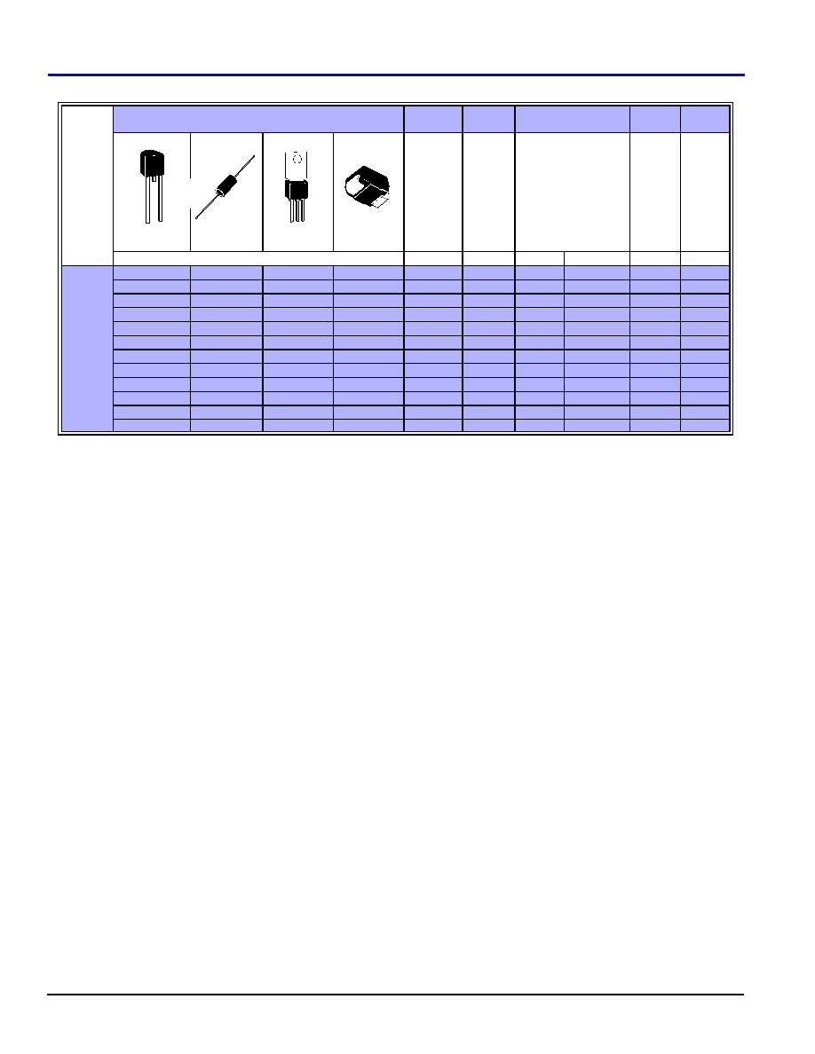
Type
Part No.
I
T(RMS)
V
DRM
V
BO
I
DRM
I
BO
TO-92
E Package
DO-15X
G Package
TO-202AB
F Package
DO-214AA
S Package
On-State
RMS Current
T
J
125∞C
50/60Hz
Sine Wave
(7) (8)
Amps
Repetitive
Peak
Off-State
Voltage
Volts
Breakover Voltage
50/60Hz Sine Wave
(1)
Volts
Repetitive
Peak
Off-State
Current
50/60Hz
Sine Wave
V=V
DRM
µAmps
Breakover
Current
50/60Hz
Sine Wave
µAmps
See "Package Dimensions" section for variations.
MAX
MIN
MIN
MAX
MAX
MAX
K1050E70
K1050G
K1050S
1.0
±90
95
113
5
10
K1100E70
K1100G
K1100S
1.0
±90
104
118
5
10
K1200E70
K1200G
K1200S
1.0
±90
110
125
5
10
K1300E70
K1300G
K1300S
1.0
±90
120
138
5
10
K1400E70
K1400G
K1400S
1.0
±90
130
146
5
10
K1500E70
K1500G
K1500S
1.0
±90
140
170
5
10
K2000E70
K2000G
K2000F1
K2000S
1.0
±180
190
215
5
10
K2200E70
K2200G
K2200F1
K2200S
1.0
±180
205
230
5
10
K2400E70
K2400G
K2400F1
K2400S
1.0
±190
220
250
5
10
K2401F1
1.0 (10)
±190
220
250
5
10
K2500E70
K2500G
K2500F1
K2500S
1.0
±190
240
280
5
10
K3000F1
1.0
±190
270
330
5
10
SIDAC
Teccor Electronics
9-3
SIDAC
(972) 580-7777
V-I Characteristics
Figure 9.1
Peak Surge Current vs Surge Current Duration
I
H
V
TM
I
TSM
R
S
dV
q
/dt
dv/dt
di/dt
Dynamic
Holding Current
50/60Hz
Sine Wave
R = 100
(3) (4)
mAmps
Peak
On-State
Voltage
I
T
= 1 Amp
Volts
Max
Peak One
Cycle Surge
Current
50/60Hz Sine Wave
(Non-Repetitive)
(5)
Amps
Switching
Resistance
50/60Hz Sine Wave
(9)
k
Critical
Rate-of-Rise
of Turn-off
Voltage at
8kHz
Volts/
µ
Sec
Critical
Rate-of-Rise
of Off-State
Voltage at
Rated V
DRM
T
J
100∞C
Volts/
µ
Sec
Critical
Rate-of-Rise
of On-State
Current
Amps/
µ
Sec
Package
60Hz
50Hz
TYP
MAX
E
G
F
S
MIN
MIN
MIN
TYP
60
150
1.5
1.5
1.5
20
16.7
0.1
20
1500
150
60
150
1.5
1.5
1.5
20
16.7
0.1
20
1500
150
60
150
1.5
1.5
1.5
20
16.7
0.1
20
1500
150
60
150
1.5
1.5
1.5
20
16.7
0.1
20
1500
150
60
150
1.5
1.5
1.5
20
16.7
0.1
20
1500
150
60
150
1.5
1.5
1.5
20
16.7
0.1
20
1500
150
60
150
1.5
1.5
3.0
1.5
20
16.7
0.1
20
1500
150
60
150
1.5
1.5
3.0
1.5
20
16.7
0.1
20
1500
150
60
150
1.5
1.5
3.0
1.5
20
16.7
0.1
20
1500
150
60
150
3.0
20
16.7
2.0
42
1500
150
60
150
1.5
1.5
3.0
1.5
20
16.7
0.1
20
1500
150
60
150
3.0
20
16.7
0.1
20
1500
150
R
S
V
BO
V
S
≠
(
)
I
S
I
B O
≠
(
)
--------------------------------
=
THERMAL RESISTANCE (STEADY STATE)
R
JC
[R
JA
] ∞C/W (TYPICAL)
E
G
F (6)
S
35 [95]
18 [75]
7 [45]
30 [85]
1.0
10
100
1000
1.0
2.0
4.0
6.0
8.0
10
20
40
SUPPLY FREQUENCY: 60 Hz Sinusoidal
LOAD: Resistive
RMS ON-STATE CURRENT: IT RMS Maximum Rated
Value at Specified Junction Temperature
BLOCKING CAPABILITY MAY BE LOST
DURING AND IMMEDIATELY
FOLLOWING SURGE CURRENT
INTERVAL
OVERLOAD MAY NOT BE REPEATED
UNTIL JUNCTION TEMPERATURE
HAS RETURNED TO STEADY-STATE
RATED VALUE.
Surge Current Duration - Full Cycles
Peak Surge (Non-Repetitive)
On-State Current [I
(TSM)
] - Amps
100
Electrical Specifications
SIDAC
9-4
Teccor Electronics
(972) 580-7777
Figure 9.2
Normalized DC Holding Current vs Case/Lead Temperature
Figure 9.3
Typical Metal Halide Ignitor Circuit
Figure 9.4
Repetitive Peak On-State Current (I
TRM
) vs Pulse Width at
Various Frequencies
Figure 9.5
Maximum Allowable Ambient Temperature vs On-State
Current
Figure 9.6
Normalized V
BO
Change vs Junction Temperature
Figure 9.7
Normalized Repetitive Peak Breakover Current vs Junction
Temperature
0
.5
1.0
2.0
1.5
-15
-40
+25
+65
+105
+125
Case Temperature (TC) -
∞
C
I H
I H
(T
C
=25
∞
C)
Ratio of
BALLAST
K2401F1
220V/240V
50/60Hz
Typical Metal Halide Ignitor Circuit
METAL
HALIDE
LAMP
H.V.
STEP-UP
TRANSFORMER
5.6K - 8.2K
5W
5 - 6µH
0.1 - 0.15 µF
0.22 - 0.33 µF
di/dt Limit Line
0.6
0.8
4
2
4
6
8
10
20
40
60
80
100
200
400
600
2 x 10⁻³
6 8
1 x 10⁻²
2
4
6 8
1 x 10⁻¹
2
4 6 8 1
1
Pulse base width (to) - mSec.
Repetitive Peak On-State Current (I
TRM
) - Amps
VBO Firing
Current
Waveform
Non-Repeated
Repetition Frequency f=5 Hz
f=10 Hz
f=100 Hz
f=1 kHz
f=5 kHz
f=10 kHz
f=20 kHz
T
J
=125∫C Max
to
ITRM
l/f
Non-Repeated
Non-Repeated
0
0.2
0.4
0.6
0.8
1.0
20
40
60
80
100
120
140
25
RMS On-State Current [IT(RMS)] - Amps
Maximum Allowable Ambient Temperature (T
A
) - ∞C
CURRENT WAVEFORM: Sinusoidal - 60 Hz
LOAD: Resistive or Inductive
FREE AIR RATING
TO-202 TYPE 1
TO-92 and DO-214
TO-202 TYPE 23 & 41
-12
-20
0
+20
+40
+60
+80
+100
+120
-10
-8
-6
-4
-2
0
+2
+4
-40
+25
Junction Temperature (TJ) - ∞C
Percentage of
V
BO
Change - %
+140
20
30
40
50
60
80
70
90
100
110 120
1
2
3
4
5
6
7
8
9
Junction Temperature (TJ) -
∞
C
Repetitiv
e P
eak Break
o
v
er
Current (I
BO
) Multiplier
V=VBO
130
SIDAC
Teccor Electronics
9-5
SIDAC
(972) 580-7777
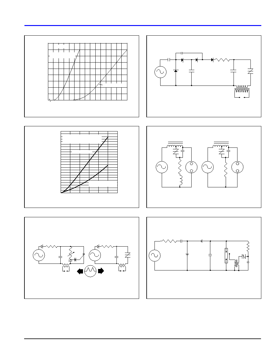
Figure 9.8
On-State Current vs On-State Voltage (Typical)
Figure 9.9
Power Dissipation (Typical) vs On-State Current
Figure 9.10
Comparison of Sidac vs SCR
Figure 9.11
Ignitor Circuit (Low Voltage Input)
Figure 9.12
Typical High Pressure Sodium Lamp Firing Circuit
Figure 9.13
Xenon Lamp Flashing Circuit
0
0.8
1.2
1.0
1.4
1.6
1.8
2.0
2.2
2.4
2.6
2.8
3.0
3.2
3.4
3.6
0
1
2
3
4
5
6
7
8
9
Positive or Negative Instantaneous On-State Voltage (vT) - Volts
Positive or Negative Instantaneous
On-State Current (i
T
) - Amps
TL =25∞C
TO-202 "F" Package
TO-92, DO-214AA & DO-15X
"E", "S" and "G" Packages
0.2
0.4
0.6
0.8
1.0
0
CURRENT WAVEFORM: Sinusoidal
LOAD: Resistive or Inductive
CONDUCTION ANGLE: See Figure 9.15
0.4
0.8
1.2
1.6
0.2
0.6
1.0
1.4
1.8
2.0
2.2
RMS On-State Current [IT(RMS)] - Amps
Average On-State Power Dissipation
[P
D(AV)
] - Watts
TO-202 "F" Package
"E", "S" & "G" Packages
TO-92, DO-214AA & DO-15X
100-250
VAC
60 Hz
100-250
VAC
60 Hz
SCR
SIDAC
4.7
µ
F
100V
10
µ
F
50V
24 VAC
60 Hz
4.7
µ
F
100V
Ω W
K1200E
SIDAC
200V
H.V.
IGNITOR
1.2
µ
F
4.7 k
- +
- +
+
-
SIDAC
120 VAC
60 Hz
16 mH
3.3 K
0.47
µ
F
400V
BALLAST
SIDAC
220 VAC
60 Hz
7.5 K
0.22
µ
F
BALLAST
LAMP
120 VAC
220 VAC
LAMP
- +
+
-
XENON LAMP
K2200F1
10
µ
F
2w
120VAC
60Hz
10
µ
F
450V
4KV
.01
µ
F
400V
20 M
SIDAC
200-
400V
100
250V
TRIGGER
TRANSFORMER
20:1


